Welcome to this tutorial on driving the SD40-2, GP38-2 and GP40-2, featured in the Sand Patch Grade (SD40-2 & GP38-2), NEC: New York (GP38-2), Peninsula Corridor (GP38-2) and CN Oakville Subdivision (GP38-2) routes as well as the GP40-2 locomotive dlc. All images are from the GP40-2 locomotive. Any questions about this tutorial can be asked in the comments section at the bottom of the page.
The SD40-2 and GP38-2 are featured in the base game, whilst the GP40-2 is available as a separate DLC only for Train Sim World 2020.
Driving the Locomotive[]
This section of the tutorial covers driving the locomotive when it has already been started. This is how the locomotive starts in services and some scenarios.
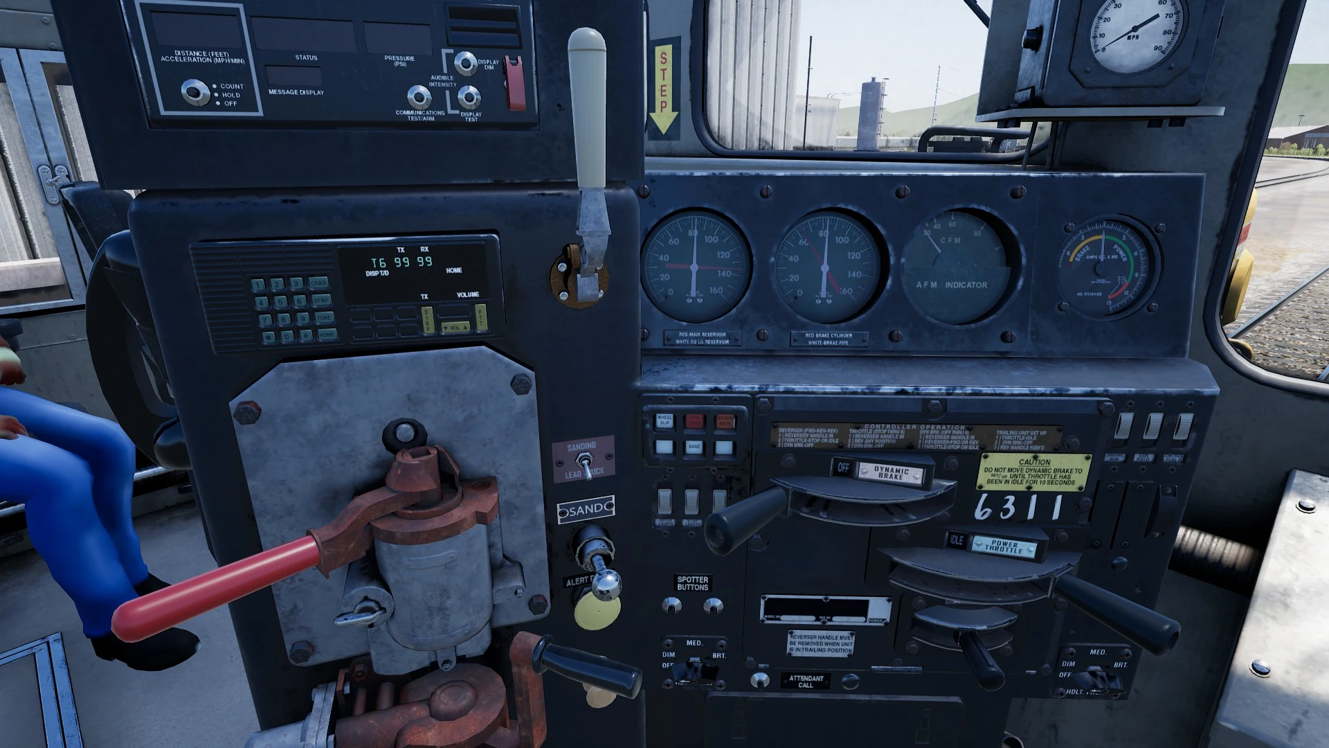
Firstly, move the independent brake to the release position, the independent brake is the black handle in the bottom left of the image. Secondly move the automatic brake, the red handle above the independent brake into the release position. The reverser is the small handle in the bottom right of the image, move this into either the forward or reverse position. Then move the throttle, which is located above the reverser into the notch 1 position. Your train should now start moving.
To stop the locomotive, move the throttle into the idle position and then apply the automatic brake. Be careful not to apply the automatic brake beyond the 'full service' position. The dynamic brake may also be used to slow the locomotive down.
Starting the Locomotive[]
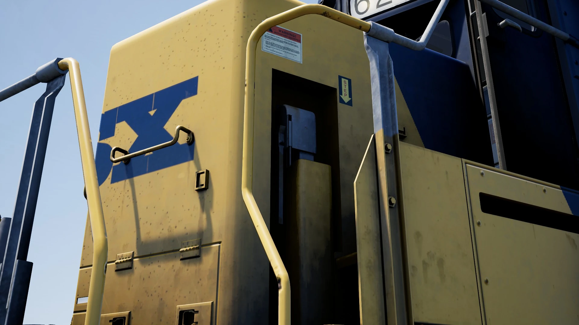
This section of the tutorial covers a cold start of the locomotives. Firstly, apply the hanbrake which is shown in the image to the right. In the GP40-2 and GP38-2 it is a handle like in the image whereas in the SD40-2 it is a wheel.
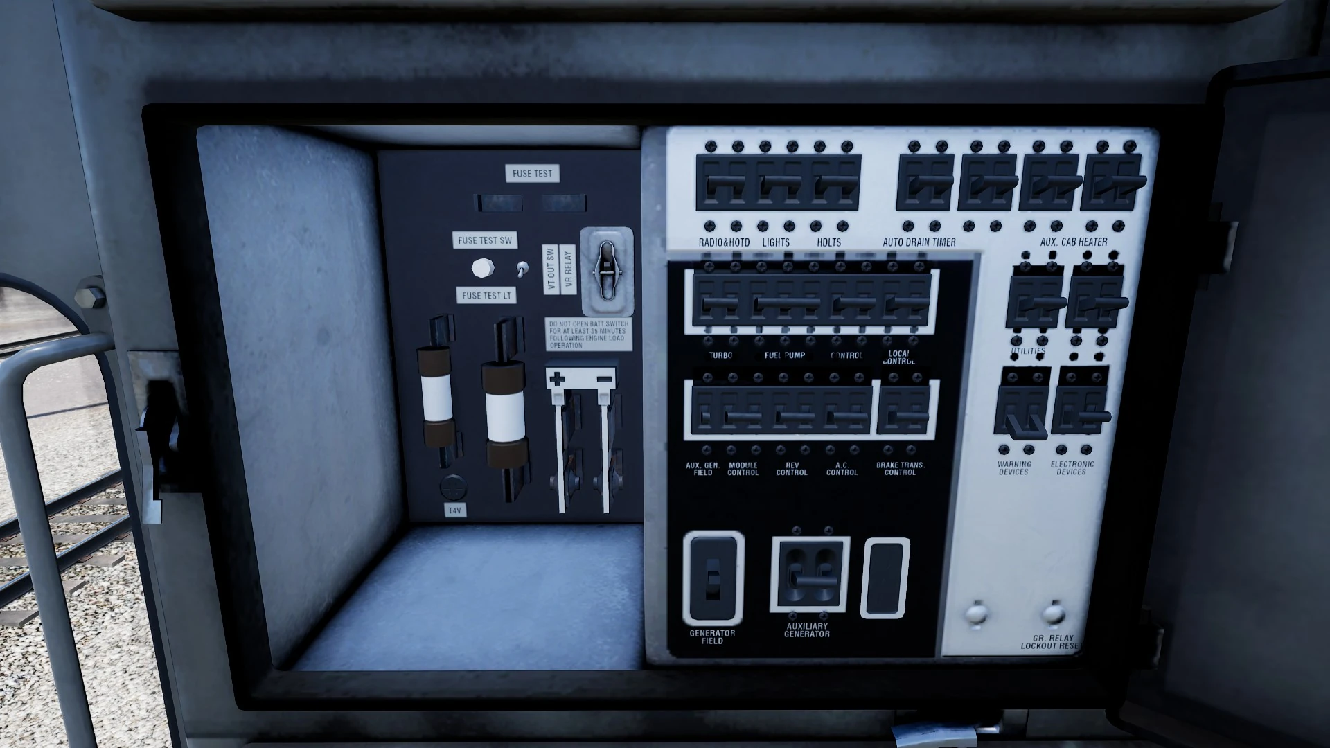
Secondly, open the fuse box, which is located behind the driver's seat and is shown in the second image. Then check that the main breaker and all of the fuses are set to the on position. Then close the fuse box door.
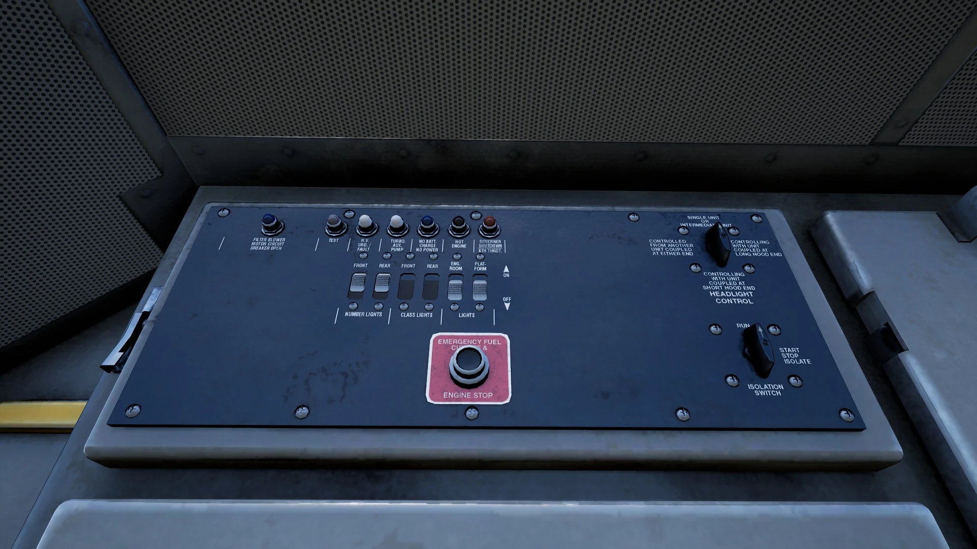
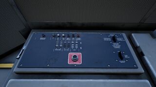
Then set the start-run switch located above the fuse box on the panel shown in the left image. Set this switch to the Start position.

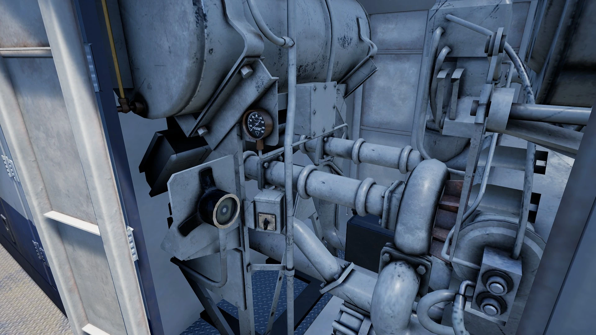
Then open the engine room doors on the long hood. The engine room will appear as shown in the image to the right. Hold the Prime/Start switch to the left position for 5 seconds. This switch is located in the centre right of the engine room. Then move it to the right to start the engine. After the engine has started, close the engine room doors. Then return to the cab and set the start-run switch to the Run position.

Sit in the engineer's seat and set the Engine Run, Field Generator and Control & Fuel Pump to the on position. These switches are located in the top right of the control console shown in the image to the left. Turn the ditch lights and gauge lights which are located to the left of the dynamic brake to the on position. Then set the headlights, which is located in the bottom right of the console, to the bright position. Then turn the Cut-off valve to the Freight position. Then set the MU-2A valve to the Lead or Dead position. Keeping the reverser in the neutral position, set the throttle to notch 1 and wait for the main reservoir to reach 140psi. Then check the independent brake is set to the maximum setting. Then release the automatic brake and wait for the equalising reservoir pressure andn the main reservoir to reach 90psi. Move the throttle back to notch 0 and release the handbrake. Now the locomotive has been started, you can now drive the locomotive.
Multiple Unit Working[]
As MU Lead[]
Ensure the locomotives have been fully set up as per the locomotive start-up instructions if required. Once the locomotives are operational then you can set them up for Multiple Unit working.
The start-up instructions will set the locomotive up to be suitable for leading a consist or being the sole locomotive in a consist.
The key settings to be aware of, should you need to change a locomotive from trailing back to lead are as shown below.
These three switches enable the power controllers (e.g. Throttle) to work:
Engine Run: ON
Generator Field: ON
Control & Fuel Pump: ON
These three valves control whether the brake handles operate the brakes on the train:
Brake Cut-off Valve: FREIGHT
MU-2A Valve: LEAD OR TRAIL
As MU Trail[]
When setting up the locomotive in a non-lead position you have several options depending on which role you want it to play in the consist:
No Power, No brakes or “Dead in Tow”[]
This is useful if you are towing a completely cold and dark locomotive. In this instance, set the control stand up as follows:
Engine Run: ON
Generator Field: ON
Control & Fuel Pump: ON
Brake Cut-off Valve: CUT-OUT
MU-2A Valve: LEAD OR TRAIL
Note: If the locomotive engine is not started then the first three switches are not important. However, if the engine is running and you just want it to sit in idle, then setting them to ON means they will ignore all signals from the lead locomotive and remain in idle.
No Power, Full Brakes[]
Engine Run: ON
Generator Field: ON
Control & Fuel Pump: ON
Brake Cut-off Valve: CUT-OUT
MU-2A Valve: TRAIL 6 OR 26
In this configuration, the power controls in the locomotive have control over the engine so the lead unit will not be able to operate it remotely. This will mean that it remains at idle and does not contribute any power to the consist. The brake settings cut out the brake handle and set it up to be driven by a connected unit in the “Lead or Trail” configuration (which your lead unit should be set to). This means the locomotive will supply additional brake force to your train.
Power and Full Brakes[]
Engine Run: OFF
Generator Field: OFF
Control & Fuel Pump: OFF
Brake Cut-off Valve: CUT-OUT
MU-2A Valve: TRAIL 6 OR 26
In this configuration, we disable the control stand for the power controls which will allow the lead unit to have full control over the power on this locomotive. As the lead unit applies throttle positions so the internal electronics of this locomotive’s stand will do the same. Brakes are also set up to be managed by the lead unit.
Distributed Power[]
When you have a consist set up with locomotives that are not directly connected, such as when you have a locomotive set at the front and another set at the rear. This requires a slightly different configuration to ensure that all locomotives function correctly in the consist. The Radio is therefore used to operate the rear locomotive.
If you have an example consist with a pair of locomotives at the front and a pair of locomotives at the rear, you would need to set up as follows:
Front Pair[]
Lead Unit: Set up as Lead and ensure the radio fuse and the Banking Comms are on
Trailing Unit: Set up as Trail
Rear Pair[]
Lead Unit: Set up as Lead and ensure the radio fuse is on. Also ensure that the Reverser Handle is in and the Reverser set to the Forward position
Trailing Unit: Set up as Trail
In this configuration when the engineer makes a throttle or brake change on the front pair lead unit, the front trailing unit will respond because it is physically connected. At the same time, a radio message is sent (this is not audible to the player) which the rear pair lead unit will react to and will follow the same settings. This will then be automatically reflected on the rear pair trailing unit through its direct connection. This system is intended to mimic the behaviour of a second engineer in the rear pair leading unit that is following the actions of the lead engineer.
When set up in this way, the engineer at the front of the train has full control over all four locomotives simultaneously.
Correct Lighting[]
When driving a locomotive, the headlights should be set to the Bright position. How to do this is already covered in the above sections. Below is a list of procedures for headlights when in multiple unit operation.
The locomotive has a switch on the wall behind the engineer’s seat that has four settings. These allow you to set up the way the headlights will work on the other locomotives in the consist.
Single Unit or Intermediate Unit[]
In this setting, the locomotive will not react to headlight instructions coming from other locomotives in the consist. The headlights, if required, must be set up using the normal switches on the control stand.
Controlling with Unit Coupled at Long Hood End[]
Use this setting if this locomotive is the controlling unit for the lighting configuration (usually this would be the lead locomotive), and the next unit in the consist is coupled to this locomotive’s long hood end.
Controlling with Unit Coupled at Short Hood End[]
Use this setting if this locomotive is the controlling unit for the lighting configuration (usually this would be the lead locomotive), and the next unit in the consist is coupled to this locomotive’s short hood end.
Controller from Another Unit Coupled at Either End[]
If this unit should respond to lighting commands from a controlling unit then use this setting.
Resetting PCS Application[]
When the Pneumatic Control Switch (or PCS) is open, the train brakes cannot be released and the throttle controls are deactivated. To operate your train again you must reset the PCS.
You can tell if it is activated by looking for the PCS OPEN light being illuminated.
If there is an alarm such as the Alerter sounding, acknowledge it (Q Key, B button on your controller).
Once the train has come to a complete stop, follow these steps:
- Set the Throttle to Idle
- Set the Reverser to Neutral
- Set the Independent Brake to Full Service
- Set the Automatic Brake to Emergency
- Wait for 60 seconds
- Release the Automatic Brake and wait for the Equalising Reservoir / Brake Pipe to return to 90psi
While the Automatic Brake is releasing, you will need to put the Throttle in to Notch 1 so that the compressor can recharge the Main Reservoir.
Once the Equalising Reservoir and Brake Pipe needles have returned to 90psi, and the main reservoir has recharged to 140psi, put the Throttle back to Idle.
You should now be able to release the Independent Brake, set the Reverser and apply Throttle.
| Guides | |
|---|---|
| Game Basics | Switching/Shunting - Loading Coal |
| American Locomotive Guides | SD40-2, GP38-2 and GP40-2 - AC4400CW - ACS-64 - ES44C4 |
| British Locomotive Guides | BR Class 43 - BR Class 66 - BR Class 101 - BR Class 166 - BR Class 377 |
| German Locomotive Guides | DB BR 1442 |
| Collectibles | CSX Collectibles - GWE Collectibles - RT Collectibles - NEC Collectibles |
| Safety Systems | The Alerter - PZB |